1. Introduction
Hollow blocks are extensively used for walls in dwelling constructions in many countries.
According to a report by Mordor Intelligence, (2023) the growth in the use of hollow concrete blocks will occur in all regions of the
world, however, the Asia-Pacific region in countries such as China, India, Malaysia,
or Singapore, among others, will experience the greatest growth, especially in the
residential segment. In Mexico, it is the constructive system most used to build envelope
walls in recent houses (Huelsz et al., 2011). Thus, it is important to understand and assess the thermal performance of this
type of envelope wall constructive system in Mexican climates. Heat transfer through
hollow block constructive systems involves two or three-dimensional conduction through
the solid material, natural air convection inside the cavities, and radiation between
air-cavity surfaces.
In Mexican climates the oscillation during the day is large and the solar radiation
is high, thus the time-dependent or dynamical model for the heat transfer through
walls must be used (Huelsz et al., 2014). The steady-state model is only helpful in estimating the heating needs in winter
for countries in temperate or cold climates with low solar radiation and small temperature
oscillation during the day compared with the difference between average outdoor and
indoor temperatures (Kuehn et al., 2001). Nevertheless, most of the heat transfer studies through hollow block constructive
systems for walls consider the steadystate model. Some of these studies analyzed the
relative contribution of the three heat transfer mechanisms: conduction through the
solid frame, and convection and radiation through the air cavities (Ait-taleb et al., 2008; Borbón et al., 2010). The relative importance varies depending on the hollow block geometry and the temperature
difference between wall surfaces. The conduction contribution decreases while convection
and radiation contributions increase as the temperature difference between wall surfaces
increases (Ait-taleb et al., 2008).
Fewer studies use the time-dependent or dynamic model to evaluate the heat transfer
of hollow block or brick walls. A pioneering work by Rao & Chandra, (1970) used an electrical resistance-capacitance (R-C) network analog method to account
for two-dimensional heat transfer. These authors did not specify how they modeled
the convective and radiative heat transfer inside the air cavities. Steady and periodic
thermal characteristics of concrete hollow blocks were experimentally obtained from
an R-C network analyzer (Rao & Dance, 1968). These characteristics were used to evaluate the thermal performance of concrete
hollow block wall sections exposed to a typical summer sol-air temperature diurnal
cycle under a tropical climate, for air-conditioned and non-air-conditioned situations,
showing that the hollow block design with two large air cavities is not thermally
efficient under this climate. Gao et al., (2004) and Sala et al., (2008) made hot box experiments and numerical simulations considering a fixed temperature
in a chamber at one side of the wall, like in air-conditioned buildings, and a temperature
change in a chamber at the other side. Gao et al., (2004) produced a linear step change of the air temperature within one chamber and developed
a theoretical three-dimensional heat transfer model including the natural convection
and radiation effects in air cavities using convective and radiative heat transfer
coefficients. The heat rate through the wall was used to compare experimental and
numerical results; slight discrepancies were attributed to imperfect adiabatic conditions
in the laterals of the experimental wall. Sala et al., (2008) produced a triangular function change in the air temperature within one chamber.
Using the measured outside and inside surface temperatures, the measured interior
and exterior ambient temperatures, and the exterior and interior surface thermal resistances,
obtained from previous experiments, they calculated the response factors of the hollow
brick wall. They used finite volume software (Fluent) to numerically obtain the response
factors, without specifying in their paper how they simulated the heat transfer mechanisms
involved. The response factors obtained from experiments and simulations were similar.
Vivancos et al., (2009) reported a model for the thermal characterization of hollow bricks based on experimental
results from a guarded hot plate in steady and dynamic conditions. The characterization
is given by the thermal resistance and two parameters that are related to the thermal
diffusivity and geometric characteristics of the brick. Other two papers proposed
models for the dynamic heat transfer through hollow block walls. Zhang & Wachenfeldt, (2009) proposed one-layer and two-layer one-dimensional models with equivalent thermal conductivity
and mass density to represent the effect of concrete walls with air cavities. Nevertheless,
these authors do not analyze the convection inside the cavities nor the radiation
between its internal walls. Li et al., (2016) developed a simplified heat transfer model of hollow blocks by using the finite element
method in the frequency domain considering the convection and radiation inside the
cavities and deriving the Conduction Transfer Function (CFT) coefficients of a hollow
block from the identified s-polynomial transfer function. They compared the predicted
surface temperature at both sides of a hollow concrete block to that measured in experiments
for time-period conditions. Huelsz et al., (2016) proposed the equivalent-homogenous-layer-set (EHLS) method, which considers the two-dimensional
conduction through the solid, natural convection inside air-cavities and radiation
between air-cavity surfaces. The method gives a thermal equivalent wall composed of
at least three homogeneous layers with time-dependent properties, which can be implemented
in whole-building simulation programs. They compared results with an experimentally
validated two-dimensional model. The total thermal load difference is up to 6% for
the air-conditioned room. For the non-air-conditioned room, the difference in the
energy transferred through the wall is up to 3.4%, and the sol-air decrement factor
and the lag-time have differences up to 7%. Barrios et al. (2017) implemented the EHLS method in whole-building simulations using Energy Plus and validated
the simulations with experimental results from a whole year of measurements in a non-air-conditioned
test hut constructed with hollow concrete block walls and a roof comprised of hollow
concrete block and T-beams. Xamán et al. (2017) employing computational fluid dynamic (CFD) simulations studied the thermal performance
of hollow blocks roof used in Mexico. They analyzed the effect of adding insulation
and a reflective material coating on the external side of the roof. Huelsz et al., (2019) evaluated five heat transfer models for hollow blocks in whole-building energy simulations.
Cherem-Pereira et al., (2020) proposed the coupling of building energy simulation software with CFD software to
consider the three-dimensional time-dependent heat transfer through hollow blocks.
The method can potentially increase the precision in the energy analysis of these
elements, but due to the high computer run time, in their study, only one wall was
modeled the others were considered adiabatic, and the simulations were limited to
one day period. Jamal et al., (2021) performed two-dimensional CFD simulations to analyze the thermal performance of three
hollow blocks submitted to sinusoidal heating on the outdoor side. They pointed out
the importance of the emissivity of the internal surfaces on heat transfer. Chihab et al., (2021) employed two-dimensional CDF simulations of the steadystate heat transfer through
two configurations of hollow block roofs to generate an equivalent homogeneous monolayer
block. Using the equivalent model, they numerically solved the transient heat conduction
equation under real conditions. They reported that convection and radiation within
the cavities significantly impact the roof’s thermal behavior. Najjaoui et al., (2022) employing two-dimensional CDF simulations analyzed the heat transfer in a steady
state through three configurations of hollow-block roofs considering the solar radiation
effect. They showed that the blocks with a larger cavity height-to-length ratio have
smaller heat transfer. (Hernández-Castillo et al., 2022) made three-dimensional CFD simulations to study the steady state convection and
radiation heat transfer through the tall cavities formed in hollow-block walls. The
effect of emissivity is analyzed, the radiative heat transfer represents more than
60% of the total heat transfer for emissivity 0.8, the common value for block materials.
Nevertheless, with the extended research on hollow-block funds in the literature,
none of these studies analyzed the relative importance of the three heat transfer
mechanisms.
The term thermal bridge refers to the portion of a constructive system that transfers
much more heat than other portions. In hollow blocks, the thermal bridge is referred
to as the solid part of the hollow block (Antar, 2010), because in general, it is assumed that the solid portions of the hollow block,
i.e. the framing path transfer much more heat than the air cavities, i.e. the in-cavity path (Kosny, 2004).
However, due to the increasing temperature difference between wall surfaces, there
are increments in the convection and radiation heat transfer through the cavities
(Ait-taleb et al., 2008), so it could be possible that the heat transfer through the in-cavity path is like
that of the framing path, or even that the in-cavity path turns into the thermal bridge
instead of the framing path. However, due to the increasing temperature difference
between wall surfaces, there are increments in the convection and radiation heat transfer
through the (Ait-taleb et al., 2008), so it could be possible that the heat transfer through the in-cavity path is similar
to that of the framing path, or even that the in-cavity path turns into the thermal
bridge instead of the framing path. No studies have been found that analyze this subject,
thus the aim of the present study is to elucidate if for hot-dry climatic outdoor
conditions and for a non-air conditioned indoor, the frame path is the main path for
the heat transfer or not.
The present work reports surface temperature measurements of an envelope wall made
of concrete hollow blocks of a non-air-conditioned house in a hot-dry climate, where
the temperature difference between wall surfaces is considerable. The results are
analyzed to study the relative importance of the heat transferred through the in-cavity
path (hollow part) of the hollow block wall with respect to that transferred through
the framing path (solid part).
The paper is structured as follows: Section 2 presents the methodology and Section
3 shows the results. The conclusion is pointed out in Section 4.
2. Methodology
This section presents the methodology used for the experiments and the analysis of
the result.
2.1. EXPERIMENTS
The measurements were conducted in a concrete hollow block wall of a non-air-conditioned
house in a hot-dry desert climate location. The house is constructed in Hermosillo,
the capital of the state of Sonora. This city is in the North-Western zone of Mexico,
275 km south of the U.S. border and 2037 km from Mexico City, at 29° 05’ North latitude.
High solar radiation levels, clear skies, and daily and annual high-temperature swings
are typical of the local climate. The maximum air temperature exceeds 38°C on an average
of 90 days of the year, including most days from early June until early September,
with minimum air temperatures of 20-25°C and a maximum of about 40-44°C. Winters are
comfortable, with minimum temperatures of 4-7°C and maximum between 25 and 30°C. The
city has almost 300 sunny days per year; in spring and summer, solar radiation can
rise up to 1000 W/m2 (LEMA, 2014; Meteotest, 2008; Regents of the University of California, 2014).
The house, shown in Figure 1, corresponds to the most repetitive pattern of housing, which has an area of 45 m2, known as “minimum housing,” and has a South-North orientation. The roof system consists
of precast beams and polystyrene panels that are a framework for a thin layer of reinforced
concrete on top. As a final finish, the roof has a waterproof membrane of white elastomeric
polymer with high solar reflectance. All walls are made of 12 cm thick concrete hollow
blocks, finished inside with white latex paint and outside with light brown acrylic
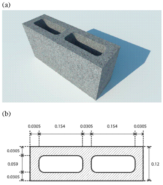
wall putty with a solar absorptance of 0.4. Figure 2 presents an image and a sketch of the hollow concrete block.
Figure 1
The house, showing the main facade (South wall) used for the measurements
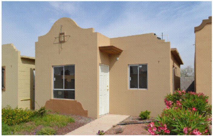
Figure 2
Concrete hollow block. (a) Image and (b) section with the dimensions, and units in
meters
The outdoor and indoor surface temperature measurements were carried out on the main
façade wall, South oriented, using temperature sensors. These measurements were carried
out on June 10-15, August 28-31, September 3-11, and October 20-31, 2011. Four Onset
TMC20-HD sensors were used, each connected to a HOBO U10 Data Logger; data were recorded
every 10 minutes. Each temperature sensor was set into a small slot on the wall using
a thermally conductive paste to ensure thermal contact. Two of the surface temperature
sensors were placed on the indoor side of the wall, one corresponding to the center
of a hollow, i.e., the center of an in-cavity path, and the other corresponding to the center of a solid
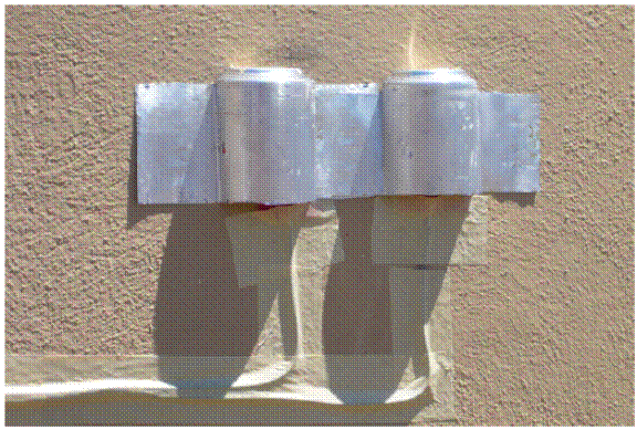
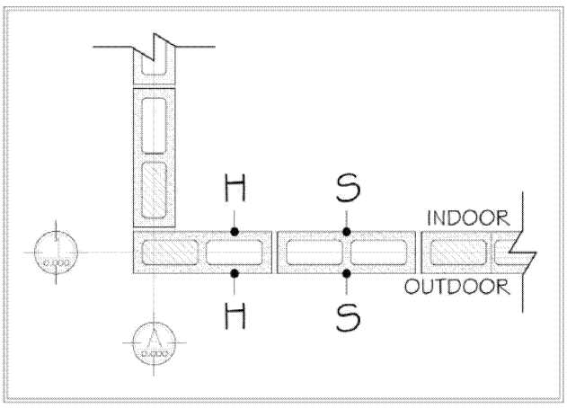
part, i.e., the center of a frame path (see Fig. 3). The other two were set at the same locations of the outdoor side of the wall; the
outdoor sensors were shielded from solar radiation using a ventilated aluminum sheet
protection (see Fig. 4). The temperature sensors had an uncertainty of 0.1oC.
Figure 3
Location of the indoor surface temperature sensors
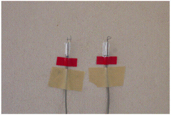
Figure 4
Location of the outdoor surface temperature sensors with an aluminum solar shield
To precisely locate the surface temperature sensors at the center of the hollow and
at the center solid part, an infrared camera was used to detect the surface temperature
differences and locate the center of each part of the block (see Fig. 5).
Figure 5
Thermography of the south façade, where the center of the hollow part (H) and the
center of the solid part (S) of the blocks can be located

2.2. ANALYSIS
The relative importance of the heat transferred through the in-cavity path (hollow
part- H) of the hollow block wall respect to that transferred through the framing
path (solid part-S) was calculated using the following methodology.
The heat transferred by unit area at any part of the outdoor surface of the wall,
qo, is given by
where ho is the heat transfer coefficient at the outdoor, Tsa is the sol-air temperature and Tso is the temperature at the outdoor surface of the wall.
The sol-air temperature is an equivalent temperature for the outdoor that considers
the heat transfer at the outdoor side of the wall by convection and radiation; it
is expressed as
where Ta is the outdoor air temperature, A is the solar absorptance of the outdoor wall surface, I is the solar radiation incident on the outdoor wall surface, and CF is the correction factor for the longwave radiation; it is taken as CF=0 for vertical walls (American Society of Heating Refrigerating and Air-Conditioning Engineers, 2009).
Meteorological data were obtained from the Meteorology station of the Energy, Environment
and Architecture Laboratory (LEMA, 2014); the solar radiation incident on the outdoor wall surface was calculated from horizontal
solar radiation and diffuse solar radiation data using transformation equations given
by (Duffie & Beckman, 2013).
The ratio of the heat transferred through the in-cavity path to that transferred through
the frame path at the outdoor surface, ro, is given by
where qoH and qoS are the heat transferred by unit area through the in-cavity path and through the
frame path at the outdoor surface, and TsoH and TsoS are the temperature at the wall outdoor surface measured at the center of the in-cavity
path and at the center of the frame path, as shown in Fig. 6. Note that ho has the same value for both H and S positions, thus it can be eliminated in equation (3).
Figure 6
Horizontal section of the wall, where the placement of the sensors in the hollow (H)
and the solid (S) part of the block can be seen, both outside and inside
Similarly, the heat transferred by unit area at any part of the indoor surface of
the wall, qi, is given by
where hi is the heat transfer coefficient at the indoor, Tsi is the temperature at the indoor surface of the wall and Ti is the indoor air temperature.
The ratio of the heat transferred through the in-cavity path to that transferred through
the frame path at the indoor surface, ri, is given by
where qiH and qiS are the heat transferred by unit area through the in-cavity path and through the
frame path at the indoor surface, and TsiH and TsiS are the temperature at the wall indoor surface measured at the center of the in-cavity
path and at the center of the frame path, as shown in Fig. 6. Also, hi has the same value for both H and S positions, thus it can be eliminated in equation (5).
The relative importance of the heat transferred through the in-cavity path (hollow
part-H) of the hollow block wall with respect to that transferred through the framing
path (solid part-S) is estimated by of ro and ri. It is worth mentioning, that ro and ri could be calculated directly by using heat flux meters at the same points where the
temperatures were recorded, nevertheless, the authors did not get the sensors on time
while they had access to the house.
3. Results
As an example, the surface temperatures measured by the four sensors during four days
in August are shown in Figure 7. The outdoor air temperature, the indoor air temperature, the sol-air temperature,
and the total horizontal solar radiation are included. It can be observed the typical
climatic conditions of a hot-dry climate, high solar radiation (near 1000 W/m2 at noon) and large oscillation amplitudes of the outdoor air temperature (larger
than 13oC) and the sol-air temperature (larger than 24oC). The temperature difference between indoors and outdoors is up to 8ºC before sunrise.
Also, it can be observed that as expected the oscillation amplitudes of the indoor
surface temperatures are smaller than that of the outdoor surface, also there is a
time lag of the indoor surface temperatures with respect to the outdoor ones. On the
same side of the block, slight differences between the temperatures of both parts
of the block can be appreciated.
Figure 7
Surface temperatures on the indoor side (Tsi) and on the outdoor side (Tso) for hollow,
H, and solid, S, parts of the block. Outdoor air temperature (To), indoor air temperature
(Ti), sol-air temperature (Tsa), and horizontal solar radiation (R), as a function
of civil time
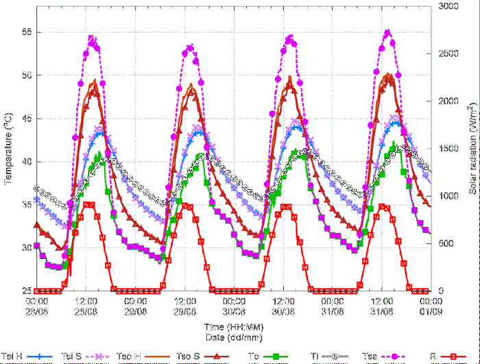
Figure 8 presents qo / ho = (Tsa -Tso) as a function of time for the same four days of Figure 7, horizontal solar radiation is included as a reference. It can be observed that heat
is transferred from the wall surface to the outdoor air during the night, while during
the daytime the heat is transferred from the outdoor air and solar radiation to the
wall surface.
Figure 8
Difference of the sol-air temperature and the outdoor surface temperature, Tsa-Tso,
as a function of civil time. Horizontal solar radiation, R, is plotted as reference
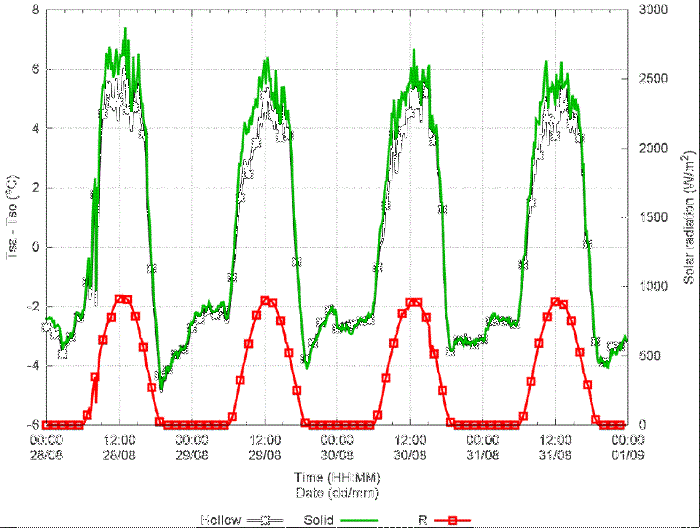
Figure 9 shows qi/ hi = (Tsi- Ti) as a function of time for the same four days. It can be observed that the heat transferred
through the indoor wall surface has a time lag with respect to that transferred through
the outdoor surface (Figure 8). From about 21:00 to 10:00 hours the heat is transferred from the indoor air to
the wall, while from 10:00 to 21:00 hours the heat is transferred from the wall to
the indoor air.
Figure 9
Difference of the indoor surface temperature and the indoor air temperature, Tsi-Ti,
as a function of civil time. Horizontal solar radiation R is plotted as reference.
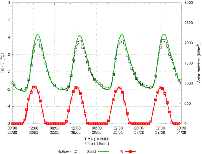
Figure 10 presents ro as a function of time for the same four days. As can be observed that during the
night, ro is around one, thus the heat transferred though the in-cavity path is practically
the same of that transferred through the frame path. Thus, during the night, the frame
path does not represent a thermal bridge. During most of the daytime, ro is greater than 0.7, thus although the frame path transfers more heat than the in-cavity
path, it cannot be considered as a thermal bridge. Close to the sunrise and sunset,
the direction of the transference of heat at one path is inverted and ro reaches low or high values.
Figure 10
Ratio of the heat transferred through the in-cavity path (hollow part-H) to that transferred
through the frame path (solid part-S) for the outdoor surface, ro, as a function of time. Horizontal solar radiation, R, is plotted as a reference
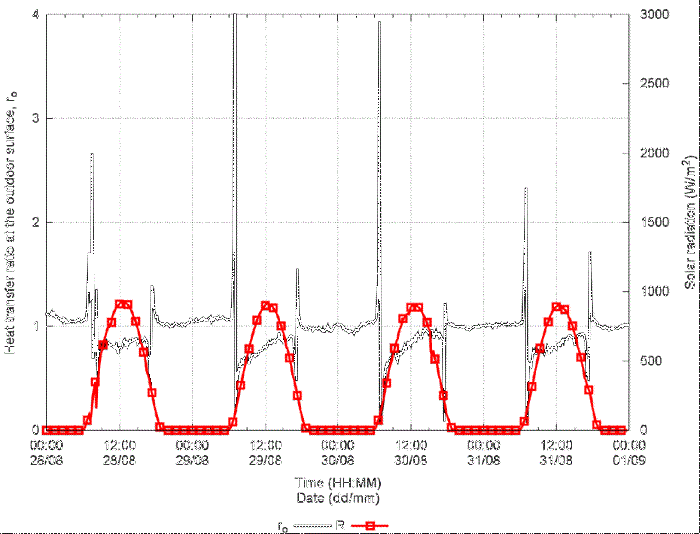
This last means that the thermal bridge is the in-cavity path for short periods. The
chute-down of the curve occurs when the heat transfer at the in-cavity path changes
direction, while the piqueup occurs when the heat transfer in the frame path changes
direction.
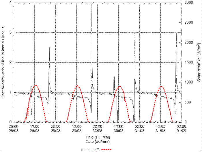
Figure 11 shows the ratio of the heat transferred through the in-cavity path (hollow part-H)
to that transferred through the frame path (solid part-S) for the indoor surface,
ri, as a function of time. Most of the time ri is greater than 0.7 and lower than 1.0, confirming that the frame path cannot be
considered a thermal bridge. There are also short periods where the thermal bridge
is the in-cavity path.
Figure 11
Ratio of the heat transferred through the in-cavity path (hollow part-H) to that transferred
through the frame path (solid part-S) for the indoor surface, ri, as a function of time. Horizontal solar radiation, R, is plotted as reference
The results for all measurements periods are like that shown in previous figures.
Not considering the short time intervals when the direction of the transference of
heat at one path is inverted at one side of the wall, implying that ro or ri reaches a low or high value, the average and standard deviation of ro and ri are taken and they are reported in Table 1. The uncertainties associated to ro and to ri due to the uncertainty of temperature measurements are smaller than the respective
standard deviation. As can be observed, for the four periods of measurements, ro and ri are close to one, which shows that the heat transferred through both paths is similar.
This result is obtained in a wall of a non-air-conditioned house in a hotdry climate
characterized by high solar radiation, large oscillation amplitude of the outdoor
air temperature, high values of the wall sol-air temperature, and high-temperature
difference between wall outdoor and indoor surfaces, conditions that promote the increase
of convection and radiation heat transfer through the hollow block air cavities (del Coz Díaz et al., 2011).
Table 1
Averages and standard deviations of the ratio of the heat transferred through the
in-cavity path to that transferred through the frame path for the outdoor surface,
ro, and at the indoor surface, ri, of the daily horizontal solar radiation maximum, Rmax, of outdoor air temperature amplitude, ΔTa, of the sol-air temperature maxima, Tsa-max, and of the maximum difference between wall outdoor and indoor surfaces temperatures,
.
|
Measurements period
|
ro
[-]
|
ri
[-]
|
Rmax
[W/m2]
|
ΔTa
[oC]
|
Tsa-max
[oC]
|
[oC]
|
|
June 10-15
|
0.9±0.1
|
0.9±0.3
|
1032±15
|
18.5±1.7
|
55.8±1.5
|
5.4±0.5
|
|
August 28-31
|
0.9±0.2
|
0.9±0.2
|
920±18
|
13.0±0.6
|
54.5±0.7
|
6.7±0.5
|
|
September 3-11
|
1.0±0.2
|
0.9±0.2
|
934±53
|
12.9±2.4
|
52.8±1.3
|
6.0±0.5
|
|
October 20-31
|
1.0±0.4
|
0.9±0.1
|
767±31
|
15.1±3.3
|
45.5±2.2
|
8.9±2.0
|
The averages and standard deviations of the daily horizontal solar radiation maximum,
Rmax, of outdoor air temperature amplitude, ΔTa, of the sol-air temperature maximum, of the sol-air temperature maximum, Tsa-max, and of the maximum difference between wall outdoor and indoor surfaces temperatures,
, are also reported in Table 1.
5. Conclusions
Dynamic heat transfer through the constructive system of a house plays an important
role in thermal performance. Hollow concrete blocks are extensively used alone or
as a part of a more complex construction system. Heat transfer through hollow concrete
blocks includes conduction in two or three dimensions, convection, and radiation through
the air cavities. It has been reported that thermal bridges are found in the solid
part, also known as the framing path, of the hollow concrete blocks.
Wall surface temperature measurements in a non-air-conditioned house in a hot-dry
climate were made to study the heat transfer through the framing part (solid part)
and the in-cavity path (hollow part) during four time periods from June to October
2011, (more than 30 days).
The heat transferred through the frame path and through the in-cavity path inside
the house are similar. The ratio of heat transferred through the frame path ri is slightly different during the night than during the day except for moments when
the direction of the heat transfer of one path is inverted, so the other path can
be considered the thermal bridge. At night, the in-cavity path transfers almost the
same heat as the frame path; during the day, the in-cavity path transfers 0.7 of the
heat transferred by the frame path. Thus, it is concluded that the frame path cannot
be considered by default as a thermal bridge and the in-cavity path as the low heat
transfer portion.
The conclusion of this work for a hollow concrete block used in a non-air-conditioned
house in a hot-dry climate is that there is no thermal bridge and further research
must be done for other hollow block geometries and materials. Understanding the heat
transfer mechanisms involved in the thermal behavior of a hollow concrete block wall
in a hot-dry climate will allow the generation of methods and guidelines for designers
and builders. This will facilitate the selection of hollow blocks for envelope walls
according to the climate and the use or not of air conditioning systems.